In the previous chapter, we have studied the pressure exerted by fluid on the wall of a container is calculated by using mathematical formula. In this chapter, we learn how to measure pressure using manometers and other mechanical gauges.
Manometers
Several instruments are used to measure pressure. A manometer is a device is used to measure pressure of a liquid by using the column of liquid. This column of liquid can be measured in vertical or inclined tubes. These devices are used for measuring different types of pressures that include absolute pressure, gauge pressure, atmospheric pressure and differential pressure.
There are different types of manometers available to measure these types of pressure. But manometers are mainly classified into two types:
- Simple Manometer
- Differential Manometer
- Simple Manometer
Simple manometers are just tubes with open top. These are attached to the vessel at its top and used to measure pressure as compare to atmospheric pressure. Simple manometers are of different types. It can be classified into:
- Piezometer:
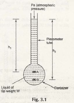
Piezometer is one of the simplest manometers with open top which is attached to a vessel containing liquid. The pressure is exerted by the liquid increases the level of liquid in the tube as shown in Fig. 3.1
Let us consider the height of point A from the upper surface of liquid in the piezometer be h1
Height of point B from the upper surface of liquid in the piezometer be h2
Pa be the atmospheric pressure
The fluid pressure at point A can be given by,
PA = h1w + Pa
The fluid pressure at point B can be given by,
PB = h2w + Pa
When both these pressures at point A and B need to be expressed in terms of gauge pressure, the term Pa will be zero. Hence, we get-
PA = h1w
PB = h2w
- U-tube Manometer:
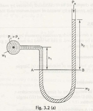
The name suggests that it is of U-shape and the raise of liquid in both the tube is considered to measure the fluid pressure as shown in Fig. 3.2 (a) Double Column Manometer (Px> Pa)
Let us consider the gauge pressure in the container be Px
Pa be the atmospheric pressure exerts on the liquid in the U-tube manometer
w1be the specific gravity of liquid in the container
w2be the specific gravity of liquid in the U-tube manometer
h1 be the height of liquid in the container up to the datum line AB
h2 be the height of liquid in the U-tube manometer up to the datum line AB
So,
The pressure exerted by liquid at A is given by,
PA = Px + w1h1
Similarly, pressure exerted by liquid at B is given by
PB = Pa+ w2h2
Or,
PB = w2h2 (Pa= 0)
We know that,
PA = PB
Px + w1h1 = w2h2
Or,
Px = (w2h2 – w1h1)
If the head of water column is considered, then the specific gravity can be given by-
Px/ w = (w2h2 – w1h1)/ w (w = specific weight of water)
Or,
Px/ w = (S2h2 – S1h1)
Here,
S1 and S2 = Specific Gravity of both liquids
Now,
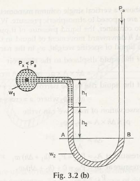
Considering Fig. 3.2 (b) Double Column Manometer (Px< Pa)
The pressure exerted by liquid at A is given by,
PA = Px + w1h1 + w2h2
Similarly, pressure exerted by liquid at B is given by
PB = 0
We know that,
PA = PB
Px + w1h1 + w2h2 = 0
Or,
Px = – (w1h1+w2h2)
If the head of water column is considered, then the specific gravity can be given by-
Px/ w = – (w1h1+w2h2)/ w (w = specific weight of water)
Or,
Px/ w = – (S1h1+S2h2)
Here,
S1 and S2 = Specific Gravity of both liquids
- Single Column Manometer:
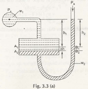
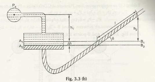
Single Column Manometer is just like u-tube manometer whose one end is replaced with a reservoir of large cross-sectional area as compare to other limb as shown in Fig. 3.3 (a)
Let us consider both the limbs of manometer are exposed to atmospheric pressure, Pa
When the limb (left one) with reservoir is connected to the container, the pressure of liquid exerts on it to push it down from A1B1 to A2B2.
The change in the level of liquid be h
h1 be the height of liquid in the container up to the line A1B1
h2 be the height of liquid in the manometer up to the line A1B1
w1be the specific gravity of liquid in the container
w2be the specific gravity of liquid in the manometer
So,
Mass of liquid displaced by liquid is given by,
m = h x A x Px
Similarly, Mass of liquid rise in the right limb is given by-
m = h2 x a x Px
According to law of conservation of masses, it can be written as-
h x A x Px = h2 x a x Px
Or,
h = h2 x a/ A
Now,
Gauge pressure at A2 is given by,
PA2 = Px + (h1 + h) w1
Similarly,
Gauge pressure at B2 is given by,
Pa2 = Pa + (h2 + h) w2
We know that,
PA2 = Pa2
Px + (h1 + h) w1 = Pa + (h2 + h) w2 (Pa = 0)
Px = (w2h2 – w1h1) + h(w2 – w1)
Or,
Px = w2h2 (1 + a/ A) – w1 (h1 + h2.a/ A)
a/A is negligible as its value is nearly zero
Hence,
Px = (w2h2 – w1h1)
Considering the Fig. 3.3 (b)
It shows an inclined manometer with an angle with horizontal then,
We know that,
Px = (w2h2 – w1h1)
= w2 sin – w1h1
Note:
Inclined manometer is considered as 25 times more sensitive than double column U-tube manometer.
- Differential Manometers
Differential manometers measure the pressure difference between two different points in two different containers. It can be classified into three differential manometers:
- Differential U-tube manometer:
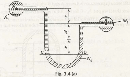
Differential U-tube manometer is similar to U-tube manometer and is used to measure pressure difference directly as shown in Fig. 3.4 (a)
Let us consider heavy liquid say mercury is present in the U-tube and it is attached to the ends of two different reservoirs.(Container A and B are placed at different heights)
w1be the specific gravity of liquid in container A
w2be the specific gravity of liquid in container B
wgbe the specific gravity of mercury in U-tube differential manometer
h1 be the height of mercury from the CD in U-tube differential manometer
h2 be the height of liquid in the container B above the mercury level
h3 be the height of liquid in the container Aup to the level of h2
We know that,
Pressure at A, PA = Pressure at B, PB
Similarly,
Pressure at C, PC = Pressure at D, PD (For Equipressure line)
PA + w1(h1 + h2+ h3) = PB+ wgh1+w2h2
PA –PB = wgh1+w2h2 – w1(h1 + h2 + h3)
= h1(wg– w1) + h2(w2– w1) – w1h3
This is the pressure difference between A and B
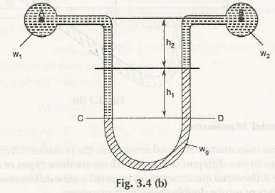
Suppose container A and B are in the same level as shown in Fig. 3.4 (b)
Here,
h1 be the height of mercury from the CD in U-tube differential manometer
h2 be the height of liquid in the above the mercury level
Now,
Pressure at C, PC = Pressure at D, PD (For Equipressure line)
PA + w1(h1 + h2) = PB + wgh1+w2h2
PA –PB= wgh1+w2h2 – w1(h1 + h2)
= h1(wg – w1) + h2 (w2 – w1)
Note:
If we put the value of h3 = 0, then same equation can be achieved from the above equation for Fig. 3.4 (a).
- Inverted U-tube differential manometer
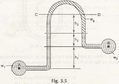
Inverted U-tube differential manometer is used to measure low pressure difference as shown in Fig. 3.5
Let us consider heavy liquid say mercury is present in the U-tube and it is attached to the ends of two different reservoirs similar to U-tube differential manometer. (Container A and B are placed at different heights)
w1be the specific gravity of liquid in container A
w2be the specific gravity of liquid in container B
wgbe the specific gravity of mercury in inverted U-tube differential manometer
h1 be the height of liquid in the container A up to the level of h2
h2 be the height of liquid in the container B below the mercury level
h3 be the height of mercury from the CD in inverted U-tube differential manometer
We know that,
Pressure at C, PC = Pressure at D, PD (For Equipressure line)
PA – w1(h1 + h2 + h3) = PB– wgh1–w2h2
PA –PB= w1(h1 + h2 + h3)– wgh1–w2h2
= h3(w1– wg) + h2 (w1– w2) – w1h1
This is the pressure difference between A and B
- Micro manometer:
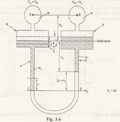
This type of manometers consists of two reservoirs having large cross-sections and contains two different liquids of different specific gravity as shown in Fig. 3.6
Let us consider standard liquid is present in the tube and it is attached to the ends of two different reservoirs. (Reservoir A and B are placed at same heights)
w1 be the specific gravity of liquid in reservoir A
w2 be the specific gravity of liquid in reservoir B
w be the specific gravity of standard liquid in the tube
h be the height of liquid (fall) in the reservoir A
h1 be the height of standard liquid (rise) in the reservoir B
h2 be the height of liquid in the reservoir B up to the initial level mark
h3 be the height of line AB up to the initial level mark
Now,
Fall of standard liquid in reservoir A = Rise of standard liquid in reservoir B = h. a/ A
We know that,
Pressure at C, PC = Pressure at D, PD (For Equipressure line)
PA+ w1(h1 + h2– h. a/ A) + w (h3 +h. a/ A) = PB+ w1 (h2 +h. a/ A) + w2h1+w (h3 –h. a/ A)
Consider h. a/ A is negligible as its value is nearly 0, then-
PA + w1(h1 + h2) + w (h3) = PB + w1 (h2) + w2h1+w (h3)
PA –PB = w1h2 + w2h1+wh3 – w1(h1 + h2)– wh3
= h1(w2– w1)
Or,
PA –PB = 2h(w2 – w1) (h1 = 2h)
This is the pressure difference between A and B
Some Basic Problems on Manometers
Example 3.1:
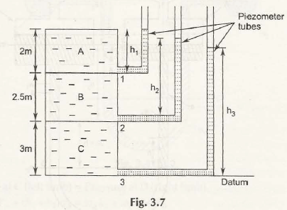
Consider the Fig. 3.7 to calculate height of liquid column in three different piezometer tubes.
Take specific gravity of three liquids as 0.8 for A, 0.85 for B and 0.95 for C.
Solution:
We know that,
Pressure, P = w x h (w = S x 1000 x 9.81 N/m3)
Where,
S = Specific Gravity of liquid
Pressure at point 1:
P1 = 0.8 x 1000 x 9.81 x 2
= 15696 N/m2
Thus,
Height of liquid column will be given by,
h1 = 15696/ (0.8 x 1000 x 9.81)
= 2 m
Pressure at point 2:
P2 = (0.85 x 1000 x 9.81 x 2.5) + (0.8 x 1000 x 9.81 x 2)
= 36542 N/m2
Thus,
Height of liquid column will be given by,
h2= 36542/ (0.85 x 1000 x 9.81)
= 4.4 m
Pressure at point 3:
P3 = (0.95 x 1000 x 9.81 x 3) + (0.85 x 1000 x 9.81 x 2.5) + (0.8 x 1000 x 9.81 x 2)
= 64501 N/m2
Thus,
Height of liquid column,h3= 64501/ (0.95 x 1000 x 9.81)
= 6.92 m
Example 3.2:
A U-tube manometer is shown in Fig. 3.8. Find the vacuum pressure at the point A.
Solution:
From the given data, the equation for finding pressure at point A can be written as-
PA + 0.2 x 0.9 x 9810 + 0.5 x 13.6 x 9810 = 0
Hence,
PA = – 98474 N/m2
Links of Previous Main Topic:-
- Introduction to statics
- Introduction to vector algebra
- Two dimensional force systems
- Introduction concept of equilibrium of rigid body
- Friction introduction
- Introduction about distributed forces
- Area moments of inertia in rectangular and polar coordinates
- Mass moment of inertia introduction
- Work done by force
- Kinematics of particles
- Position vector velocity and acceleration
- Plane kinematics of rigid bodies introduction
- Combined motion of translation and rotation
- Rectilinear motion in kinetics of particles
- Work and energy
- Linear momentum
- Force mass acceleration
- Simple stress introduction
- Normal strain
- Statically indeterminate system
- Introduction to thermodynamics
- Statement of zeroth law of thermodynamics with explanation
- Heat and work introduction
- First law of thermodynamics for a control mass closed system undergoing a cycle
- Open system and control volume
- Conversion of work into heat
- Introduction to carnot cycle
- Clausius inequality entropy and irreversibility introduction
- Ideal gas or perfect gas
- Introduction about air standard cycles
- Properties of pure substances introduction
- Vapour compression refrigeration cycle introduction
- Basic fluid mechanics and properties of fluids introduction
- Fluid statics introduction
Links of Next Mechanical Engineering Topics:-
- Fluid kinematics
- Lagrangian method for describing fluid method
- Eulerian method for describing fluid method
- Lagrangian relationship from eulerian equations
- Steady and unsteady flows
- Uniform and non uniform flows
- Stream line
- Path lines
- Streak lines
- Acceleration of a fluid particle
- Continuity equation
- Continuity equation in three dimensions in differential form
- Continuity equation in a cylindrical polar coordinate system
