To generate an alternating voltage can be generated either by rotating coil in magnetic field that is uniform in nature at a constant speed or by rotating a magnetic field that is uniform within a stationary coil at constant speed. In small AC generators, the coil rotates between the magnetic field, whereas in large AC generator magnetic field is rotated around (figure B).
Fig. A Fig. B
In each of the above-mentioned case, the amount of current generated depends upon certain factors like,
- The rotating speed of the magnetic coil
- the available number of turns that the coil contains
- And the strength of the entire field
Major equations of alternating voltages and currents
Michael Faraday, a renowned physicist, has given out Faraday’s laws electromagnetic induction concept is explained by Faraday’s laws which shows relation between electric circuit and magnetic field. This law is the basic working principle of the most of electrical motors, generators, transformers, inductors etc.
The Electromagnetic Induction law of Faraday known as Faraday’s second law states that, the magnitude of induced emf is equal to change rate of flux linkages with the coil. The flux linkages are product of number of turns and the flux associated with coil.
The shape of the wave of voltage is going to be determined by this flux distribution in the air gap. And a plane that is perpendicular to the direction of the flux will produce the maximum flux linkages with the coil when the field is uniform between the poles.
Formula suggested by Faraday’s law
As per the above diagram, the coil with N number of turns rotates in the magnetic field having magnetic flux ‘Φ’ at an angle ‘θ’ with respect to the magnetic field with an angular velocity ‘ω’, then the electromagnetic field (emf) generated in the coil, according to Faraday’s equation, is
e= -N (dΦ/dt) ……………………….. (Equation 1)
Where N= no. of turns
dΦ/dt = rate of change of magnetic flux through coil
Φ= Φmax Cos ωt ………………..(Equation2)
Where Φmax= maximum flux through coil
From Eq.1 and Eq. 2, we derive that
e= -Nd (Φmax Cos ωt)/dt
Since d(Cosωt)/dt = -ωSinωt
e= NΦωSinωt
e= NΦωSinθ ….(Equation3)
Now if the coil is perpendicular to the magnetic field then θ=90°, then the maximum induced emf will be
e= NΦωSin90°
So, Emax = NΦω (since sin90= 1) ………(Equation4)
Replacing Eq. 4 in Eq.3
e= Emax Sinθ
Similarly, if the load is resistive then the induced instantaneous current (i) is
i= Imax Sinθ
Wave forms:
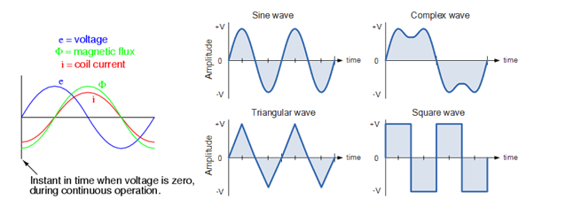
Any curve that is showing the shape of the signal. It gives out a representation of how A.C. changes with the time. The simplest possible AC waveform is the sine wave.
The above figuress how different types of wave forms. You must notice that each wave cycle replicates the other wave-cycle. Also an altering voltage and current in machines usually use both positive as well as the negative movement of the waves.
Other points to remember about wave forms are,
- Sine wave frequency is always measured in megahertz or gigahertz, and an idol wireless signal has this type of waveform
- Any other waves deviating from sine waves like saw tooth or square waves are termed as irregular and distorted
- A combination of the instantaneous amplitudes of two sine waves results in Complex waves. These complex waves are nay waves that depart from standard sine waves form.
Links of Previous Main Topic:-
- Current Electricity Basic Concepts
- Introduction to Alternating Current
- Generation and Equation of Altering Voltages and Currents
Links of Next Electrical Engineering Topics:-
- Alternating Voltage and Current
- Single Phase Circuits
- General Aspects in Single Phase
- Transients Example
- Introduction Three Phase A C Circuits
- Magnetic Field
- General Aspects
- Elementary Theory of Ideal Transformer
- General Aspects Polyphase Induction Motors
- Single Phase Motors
- Characteristics of D C Generators
- Measuring Instruments
- Power Supply System


